Inter-Module Connections & Lateral Load Transfer in Multi-Story LGS Modular Construction: A 2026 Specifier & Procurement Guide
A 2026 structural engineering and procurement guide to inter-module connections in multi-story LGS modular buildings: axial load paths, diaphragm shear transfer, thin-steel limit states, and factory QA hold points.
When commercial developers, general contractors, and structural engineers move from single-story projects to multi-story LGS modular construction, inter-module connections (IMC) become a key procurement interface. The specification must explain how separate factory-finished boxes transfer compression, uplift and lateral forces, and how site crews will install and inspect those connections.
Quick answer: Specify the building's stability system first, then assign each inter-module joint a defined load-transfer role, a calculated or tested resistance, an installation method and an inspection hold point. A strong bolt alone does not establish the capacity of the surrounding thin steel. Do not release connection fabrication while either the load path or tool access remains unresolved.
Reviewed: 11 November 2026. Scope: global procurement guidance in English for multi-story, load-bearing cold-formed steel (CFS/LGS) volumetric modules. Some systems use corner posts, a separate braced core or a primary frame; this guide does not prescribe their design or establish a permitted building height. Local adoption, code edition, site loads and approval procedures govern. The comparison and budget below are editorial decision aids, not connection test reports, approved details or project quotations.
In conventional site-built construction, connections and diaphragm joints are also necessary. Volumetric construction adds transportable structural boundaries, often concealed by finishes before erection. Procurement must resolve those boundaries before manufacturing, rather than assume the boxes will behave as one rigid structure after stacking.
Use this guide to compare connection families, allocate factory and site responsibilities, and prepare an inspection-ready tender. If the supplier's scope is still unclear, send GFK Commercial a project brief identifying the destination, module layout, intended stack height and required engineering deliverables.
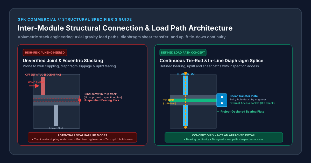
Figure 1: Conceptual comparison of an unverified joint and a connection with defined bearing, uplift and shear paths. Not to scale; no capacity, dimensions or certification are established by this illustration.
1. The Physics of Modular Stacking: Dual Load Paths in CFS
To specify and procure inter-module connections effectively, procurement teams and project managers must understand how structural forces navigate through a stacked modular building. Volumetric LGS structures must satisfy two distinct, simultaneous load paths: the Vertical Load Path (gravity, live loads, and overturning uplift) and the Horizontal Load Path (wind shear, seismic actions, and diaphragm torsion).
+-----------------------------------------------------------------+
|                        UPPER MODULE                             |
|  [Wall Stud]                [Floor Joist]          [Wall Stud]  |
+------|----------------------------|---------------------|-------+
       | Axial Compression          | Diaphragm Shear     | Uplift Tension
       V                            V                     ^
===================================================================
       INTER-MODULE CONNECTION INTERFACE (MATE-LINE / STACK)
   - Stud-over-Stud Bearing Plates (project-designed)
   - Diaphragm Shear Plates (hole/slip detail by engineer)
   - Vertical Tie-Rods / Tension Hold-Downs (where required)
===================================================================
       | Axial Compression          | Diaphragm Shear     | Uplift Tension
       V                            V                     ^
+------|----------------------------|---------------------|-------+
|  [Wall Stud]               [Ceiling Joist]         [Wall Stud]  |
|                        LOWER MODULE                             |
+-----------------------------------------------------------------+
A. The Vertical Load Path: Gravity Compression and Overturning Uplift
The vertical load path governs how the weight of the building, occupants, and lateral overturning moments travel down to the foundation.
- Gravity Axial Compression: Dead and imposed loads accumulate down the building. Determine whether each module bears through wall studs, reinforced corners or another support arrangement. Verify the entire route through floor and ceiling edge members, bearing interfaces and foundations; contact between two tracks alone does not demonstrate a complete load path.
- Stud-over-Stud In-Line Framing: Align load-bearing elements wherever the system relies on direct bearing. The engineer must define acceptable offsets and check eccentricity, track bending, local crushing and any transfer member. There is no universal 3 mm module-stacking tolerance or minimum bearing-plate thickness established by this guide. The applicable framing provisions must be checked for the actual configuration and adopted edition.
- Overturning Uplift Resistance: Wind and seismic actions can create tension at different positions as loading reverses. Tie-rods or discrete hold-downs may transfer that tension to the foundation. Their couplers, anchorage and supporting members need compatible capacities and deformation assumptions; a continuous rod is one option, not a mandatory solution for every modular system.
B. The Horizontal Load Path: Diaphragm Shear and Torsion
- Diaphragm Action: Establish how each module's floor diaphragm transfers lateral action to the selected walls, bracing or core. Neither floor nor ceiling sheathing should be credited with structural resistance without a designed assembly and fastening schedule.
- Inter-Module Diaphragm Splices: Where the design requires continuity between adjacent modules, detail shear connections, chords and collectors across the mate-lines. Check forces in both plan directions and effects from openings or torsion. The Steel Construction Info modular guidance describes both stability provided by modules and arrangements supported by separate structures; the selected arrangement controls the connection role.
- Inter-Story Drift Compatibility: Include joint slip and connection deformation in the building analysis where significant. Slotted holes may permit erection adjustment but also permit movement unless restrained by an approved detail. Specify project-specific wind serviceability, seismic displacement and facade movement criteria instead of applying a single drift ratio across jurisdictions.
2. Limit States and Failure Modes in Thin-Walled Cold-Formed Steel
Details used for hot-rolled structural steel or shipping-container corner posts cannot be transferred to a thin-walled CFS assembly without checking the connected members. Larger bolts and higher installation torque do not by themselves establish a stronger connection.
The connection must be checked against the cold-formed steel provisions adopted for the project, such as AISI S100, AS/NZS 4600 or the applicable Eurocode provisions. Member thickness, steel grade, hole geometry, load direction and connection eccentricity all affect resistance. A specification name or bolt grade is not a substitute for a calculation or a test covering the actual assembly.
1. Bolt Bearing Deformation and Sheet Tear-Out
The thin connected sheet can govern before the bolt reaches its nominal shear resistance. Check bearing deformation, tear-out, edge distances, spacing and combined actions for the actual thickness and hole type. A washer distributes clamping pressure but does not automatically repair inadequate sheet bearing or edge distance. Reinforcement needs a defined load-transfer route into the framing.
2. Net Section Rupture
Holes reduce the available section in tension. Check the remaining net section, staggered layouts where relevant, and other applicable rupture modes around the fastener group. Do not assume that adding more bolts always increases assembly capacity; additional holes may weaken a narrow strap or track.
3. Track Web Crippling and Local Bearing
A concentrated stud or post reaction can distort an unsupported track or edge member. Check the bearing length, support conditions, offset and local member resistance. Bearing plates, stiffeners or transfer members must be sized for the load and supported geometry. A generic 3 mm plate is not an approved fix for every interface.
4. Flange Prying Action and Local Distortion
An eccentric bracket can bend the supporting flange and increase fastener tension. Review bracket stiffness, fastener position and local reinforcement together. Any backing block or nested member must be part of the engineered detail, including durability and fire requirements; an improvised filler does not establish resistance.
5. Screw Pull-Out, Pull-Over and Cyclic Behavior
Screws can be legitimate structural fasteners in designed CFS assemblies. Their suitability depends on the substrate, engagement, fastening pattern and relevant design or test evidence. Do not substitute an unverified self-drilling screw for a designed inter-module connector. Likewise, a proprietary blind bolt approved for a thick hollow section is not automatically suitable for a thin track.
Inspection distinction: Installation torque is not a direct measurement of bolt preload. Use the specified snug-tight, pretensioned or proprietary installation procedure and its acceptance method. Torque-only checks are appropriate only where the approved procedure defines and validates them. Preserve the manufacturer's installation instructions with the project inspection and test plan (ITP).
3. Engineering Typologies Comparison: Inter-Module Connections
Choosing the right connection typology dictates not only structural performance but also crane cycle times, site labor costs, and the extent of post-erection finish repairs. The following matrix compares the six primary engineering approaches utilized in multi-story LGS volumetric construction.
| Connection Typology | Primary Structural Role | Thin-Steel Limit State Risk | Site Erection & Access | Interior Finish Impact | Evidence Required Before Selection |
|---|---|---|---|---|---|
| 1. Continuous Vertical Tie-Rod System | Uplift and overturning tension | Rod anchorage, bearing plates and couplers can govern | Chases and coupler access must remain available | Can preserve finishes with planned access | Rod, anchor and supporting-member calculations; installation and tensioning procedure |
| 2. Bolted External Gusset Plates with Access Pockets | Shear and/or retention as designed | Sheet bearing, tear-out and local bracket bending | Exterior work platform and tool clearance required | Can avoid interior opening where exterior access is feasible | Assembly calculations, bolt/hole schedule and weather/fire closure detail |
| 3. Proprietary Blind Fasteners | Shear and/or tension within tested scope | Substrate thickness and local deformation can govern | One-sided installation; tool and hole tolerances still matter | May reduce opening size | Current assessment or test data covering actual thickness, grade and loading; local acceptance |
| 4. Self-Aligning Gravity & Pin Interlocks | Positioning and possibly shear | Local bearing and incomplete engagement | Can assist placement; temporary stability still required | Depends on locking and inspection access | Verified engagement, restraint and resistance; cyclic evidence where required |
| 5. Perimeter Diaphragm Shear Straps | Diaphragm continuity and tension ties | Net section, screw resistance and slip | Requires access along the fastening line | May need removable floor or ceiling strips | Strap and fastening calculations or tests; installation inspection criteria |
| 6. Field-Welded Corner Splice Plates | Shear, tension or moment as designed | Thin-sheet heat damage and local member resistance | Qualified procedure, safe access and hot-work controls | Requires finish protection and planned reinstatement | Applicable welding standard, qualified procedure, specified inspection and coating repair |
These are comparison families, not a ranking of tested capacities or measured installation speeds. Select by the complete assembly and site constraints. Crane release is governed by the approved erection and temporary-stability plan, even when a joint appears fully bolted.
4. The Accessibility Dilemma: Solving the "Blind Joint" Trap
In factory-built modular construction, a high level of off-site completion can conceal the steel interface behind insulation, gypsum board, cabinetry and cladding before the module leaves the plant.
However, this creates a profound engineering contradiction: How do site ironworkers connect two fully finished boxes when the structural joints are concealed behind pristine interior drywall and exterior cladding?
                  THE ACCESSIBILITY DILEMMA

   High Factory Completion                Structural Joint Access
   (Drywall, Paint, MEP done)   <=====>   (Need access to tighten &
                                           inspect structural bolts)
                   \                     /
                    \                   /
                     V                 V
               THE "BLIND JOINT" DISASTER
               - Drywall smashed open on site
               - Repainting & patching costs
               - Compromised fire & acoustic seals
               - Delayed municipal sign-offs
Without planned access, site crews may need to reopen finished assemblies, install the connectors and reinstate the fire, acoustic and weather layers. Price this work explicitly; its cost and effect on the programme depend on the project.
Two access strategies to evaluate during shop-drawing review are:
Strategy 1: Pre-Engineered External Access Pockets
The factory reserves openings aligned with the connection nodes. Size them around the actual bracket, tool swing, gloved hand clearance and inspection sightline; a mock-up is more useful than a generic pocket dimension.
- Set and temporarily stabilize the modules under the approved erection sequence.
- Install the scheduled plates and fasteners using the approved tightening method. Do not enlarge holes or remove framing without an accepted repair detail.
- Complete the specified inspection while the connection remains visible. Record the joint identifier and drawing revision.
- Reinstate insulation, air and water barriers and cladding using the accepted closure assembly. Structural sign-off does not establish fire or envelope performance.
- Record closure evidence before the work becomes concealed, including any required fire-stopping inspection.
Strategy 2: Removable Interior Architectural Trim Hatches
Where exterior access is unavailable, reserve an interior access zone behind a removable panel, baseboard or ceiling reveal. Coordinate the opening with the structural and fire/acoustic designers before manufacturing. An access hole cut into a track or structural sheathing can reduce resistance even if it is later covered.
Use a full-size mock-up to demonstrate fastener installation and inspection with adjacent modules and finishes in place. A decorative cover does not itself provide a fire rating. Specify the complete rated or assessed closure assembly and identify who inspects its reinstatement. If neither access strategy works, reconsider the connection or finish sequence before ordering the modules.
5. Tolerances, Shimming, and Laser Metrology in Stacked Construction
In modular construction, tolerance control connects factory measurements to site fit-up. Agree a tolerance schedule that covers module length, diagonals, bearing levels, connection-hole positions, foundation survey and the cumulative erected stack. Machine positioning accuracy alone does not describe the finished module after welding, handling or transport.
A. The Compounding Error Dilemma
Illustrative arithmetic, not an acceptance limit: If three tiers each contribute a 3 mm deviation in the same horizontal direction, the total is 9 mm. Actual deviations may differ in direction and magnitude, and the erection survey must distinguish overall out-of-plumb from relative joint misalignment. Do not compare every deviation against a single tolerance value.
The drawing package should state the survey datum, measurement method, permitted adjustment and stop-work criterion. Check foundation levels and anchor positions before shipment, then compare module identifiers and mating dimensions before the lift sequence starts.
B. Engineering Rules for Structural Shimming
- Material and Bearing Area: Specify the shim material, footprint, strength, corrosion protection and retention in the approved bearing detail. Do not insert improvised scrap, plastic or timber into a structural bearing path.
- Load Transfer: Confirm that the shim bears on members able to receive the reaction. Full contact with an unsupported track does not by itself establish adequate support. Check plate bending, local bearing and effects on adjacent fasteners.
- Thickness and Adjustment: Establish the permitted pack thickness and layer arrangement before erection. This guide provides no 6 mm exemption or universal 12–19 mm review threshold. Changes can affect bolt grip, bending, prying, engagement and the geometry of weather or fire seals; deviations require the project's defined engineering disposition.
C. Metrology and Pre-Fit Verification
Choose measurement equipment appropriate to the agreed accuracy and access, whether survey instruments, jigs or laser scanning. A digital model is useful only when it represents measured geometry and a controlled coordinate system. Request the actual inspection record rather than a generic statement that the factory uses BIM.
For a new or difficult interface, consider a trial stack or representative connection mock-up before dispatch. Define which dimensions, tool clearances, engagement checks and closure steps it must demonstrate, who witnesses it and how deviations are resolved. A successful fit-up does not replace structural capacity verification.
6. Factory vs. Site Scope Allocation Matrix
A primary source of contractual disputes in modular construction is the ambiguity surrounding who supplies the connection hardware, who verifies alignments, and who performs site bolting. The matrix below is a proposed tender allocation to confirm in the contract; responsibilities and statutory signatories vary by jurisdiction.
| Interface / Task | Proposed Factory Deliverable | Proposed Site / Local Design Deliverable | Hold Point & Sign-Off Record |
|---|---|---|---|
| Structural Design | Module geometry, material data, connection design inputs and reactions | Named engineer of record coordinates building stability, foundations and locally required approvals | Agreed design-responsibility schedule and accepted drawing/calculation revisions before fabrication |
| Hole Prep & Fabrication | Holes and brackets to the approved drawing and tolerance schedule | Verify foundation survey and anchor layout against the same datum | Dimensional inspection report with module and joint identifiers |
| Hardware Supply | Scheduled plates, rods, couplers, fasteners and traceability records | Provide approved access equipment, installation tools and temporary works | Hardware receipt and certificate check before installation |
| Access & Bolting | Openings, bracket locations and installation instructions | Install and inspect using the accepted fastener procedure | Hold Point 1: Joint inspection record before concealment |
| Pocket Closure | Compatible closure components and assembly details within contracted scope | Reinstate and inspect fire, acoustic, air and water layers | Hold Point 2: Required fire/envelope inspection and closure photographs |
| Leveling & Tie-Down | Engineered bearing/shim details and tension-system instructions | Survey each tier and adjust/tension within the approved method | Hold Point 3: Survey and installation records accepted by the designated responsible party |
Resolve missing responsibilities before comparing bids. If the project is ready for supplier clarification, submit the interface schedule with your inquiry and request written confirmation of inclusions, exclusions and local engineering responsibilities.
7. Procurement and Engineering Checklist
Use this 4-stage engineering checklist during tender clarification, pre-production review, factory fabrication, and on-site module erection.
Stage 1: Structural Tender & Design Review
- Record the locally adopted building code, referenced standards and editions; do not assume the latest publication is the adopted requirement.
- Name the engineer responsible for overall stability and for interfaces between module, foundation and any separate core or frame.
- Map compression, uplift, diaphragm shear, collectors and robustness ties to joint identifiers.
- Include connection stiffness/slip assumptions, load combinations and serviceability criteria in the design brief.
- Accept bearing offsets, plate sizes and shim limits through the engineered details.
Stage 2: Hardware Sourcing & Fastener Specification
- Specify the complete bolt/nut/washer or proprietary fastener assembly and its installation method; do not treat different regional grades as interchangeable.
- Verify that any product assessment covers the actual substrate thickness, hole configuration, load direction and exposure.
- Agree coating compatibility, exposure class and repair procedures; select protection for the environment rather than a universal coating thickness.
- Identify every plate and hardware batch against the erection drawings and retain material records.
Stage 3: Factory Acceptance Test (FAT) & Quality Control
- Inspect connection-hole positions and bearing geometry against the project tolerance schedule.
- Specify applicable welding procedures and visual or other examination requirements; select inspection methods for the actual joint.
- Review access openings for structural, fire and acoustic effects before cutting framing or sheathing.
- Demonstrate representative fit-up and tool clearance where required by the inspection plan.
- Record unresolved deviations and obtain accepted dispositions before dispatch.
Stage 4: On-Site Erection, Installation Inspection & Closure
- Survey foundation anchors and bearing levels before mobilizing the crane.
- Follow the engineered lift plan, including project-specific weather limits, rigging, temporary bracing and crane-release criteria.
- Install approved bearing packs and survey each tier before stacking proceeds.
- Follow the specified fastener tightening procedure and record the required acceptance evidence, not an assumed torque-to-preload conversion.
- Link inspection results, tool calibration where relevant and any repairs to individual joint identifiers.
- Obtain the required structural and fire/envelope inspections before closing the pockets or interior hatches.
8. Worked Procurement Budget Example: Access Pockets vs. Reactive Drywall Rework
Hypothetical budgeting comparison in USD, not measured project data or a GFK quotation: Assume a three-story hotel with 24 modules, eight per floor and two stacked interfaces. For this example only, assume four separately priced access nodes per module at each stacked interface: 8 × 2 × 4 = 64 nodes. Real node counts must come from the connection schedule; shared connections and side-by-side ties can change the total. All unit rates below are invented estimating inputs for demonstrating the method, not market benchmarks.
+--------------------------------------------------------------------------+
|                    WORKED COST COMPARISON (64 JOINTS)                    |
+--------------------------------------------------------------------------+
| METHOD A: Pre-Engineered External Access Pockets                         |
|   - Factory CNC pocket framing & flap prep   : $50 / node                |
|   - Site ironworker exterior bolting labor     : $70 / node              |
|   - Weather flap & insulation closure        : $40 / node                |
|   - TOTAL PER NODE                           : $160                      |
|   --------------------------------------------------------------------   |
|   TOTAL PROJECT COST (64 NODES)              : $10,240                   |
+--------------------------------------------------------------------------+
| METHOD B: Unplanned "Blind Joints" (Post-Erection Drywall Cutting)       |
|   - Interior drywall sawcut & demo           : $95 / node                |
|   - Difficult blind bolting & wrenching      : $180 / node               |
|   - Acoustic/fire batt reinstatement         : $65 / node                |
|   - Drywall patch, mud, tape, sanding (3 coats): $210 / node             |
|   - Full room wall repainting (matching color): $175 / node             |
|   - Defect reinspection fee allowance        : $45 / node                |
|   - TOTAL PER NODE                           : $770                      |
|   --------------------------------------------------------------------   |
|   TOTAL PROJECT COST (64 NODES)              : $49,280                   |
+--------------------------------------------------------------------------+
| NET SAVINGS VIA PRE-ENGINEERED ACCESS        : $39,040 (79% Reduction)   |
| Schedule impact requires a project-specific programme comparison.        |
+--------------------------------------------------------------------------+
Commercial Takeaway
The assumed planned-access cost is 64 × ($50 + $70 + $40) = $10,240. The assumed rework cost is 64 × ($95 + $180 + $65 + $210 + $175 + $45) = $49,280. The difference is $39,040, or 79.2% of the assumed rework cost, rounded to 79% in the chart. This is not a forecast saving or a percentage of the whole building budget.
Before using the comparison in a tender, add scaffold or platform mobilization, crane standby, engineering, inspection, permits, taxes, contingency and any difference in connector or rated-closure costs. Confirm whether repainting is priced per node or per room to avoid double counting. Change node count, labor productivity and rates using local quotations; no handover time saving is established by this example.
9. Frequently Asked Questions
Why do inter-module connections (IMC) require different engineering from standard stick-built cold-formed steel?
Volumetric construction adds structural boundaries between transportable boxes. The design must transfer the required compression, uplift and diaphragm forces across those boundaries while allowing installation and inspection. A separate core or primary frame may provide overall stability, so the connection role depends on the selected building system.
What is the primary risk of using blind screws or unreinforced fasteners at modular stack joints?
An unverified connector can fail through sheet bearing, tear-out, pull-out or local distortion before its nominal fastener rating is reached. Screws and blind fasteners can be suitable when designed or tested for the actual assembly. Their inspection method follows the approved installation procedure; torque checking is not a universal acceptance test.
How does in-line stud framing prevent track web crippling in stacked modular buildings?
Aligning bearing elements reduces eccentric load transfer, but the tracks and supporting members still require local checks. The engineer defines the permitted offset, bearing length and any reinforcement for the actual load and geometry. This guide does not establish a universal 3 mm stacking tolerance or bearing-plate thickness.
What is the difference between a continuous vertical tie-rod and an inter-module shear tie plate?
A vertical tie-rod primarily carries tension associated with uplift or overturning, through designed couplers and anchors. A shear plate transfers specified forces between connected module members or diaphragm edges. Neither component alone establishes a complete building load path; the surrounding members and foundations must also be checked.
How can developers plan bolt access without destroying interior drywall?
Reserve external pockets or removable interior access zones during factory detailing, then demonstrate tool clearance with the adjacent module in place. Keep connections visible through the specified inspection hold point. Reinstate the approved fire, acoustic and weather assemblies afterward; a decorative trim panel alone does not establish their performance.
What structural shim thickness is permitted between stacked LGS modules before requiring engineering review?
Use the material, bearing area, pack thickness and retention specified in the engineered interface detail. There is no general 6 mm exemption or universal review threshold established here. Changes outside the accepted detail require the project's engineering review process because they can affect bearing, bolt grip, prying and closure geometry.
10. Sources and References
Source note, 11 November 2026: The modular construction guidance below was accessible during this review. The other links are retained publisher/code reference portals, not evidence that a particular edition, clause or project detail was checked. No quoted standard clause, numerical connection capacity or blanket approval is asserted by this guide. Obtain the applicable documents and confirm local adoption with the responsible designer.
- Steel Construction Info — Modular construction: Industry technical guidance describing module structural forms, bolted site connections and alternative stability arrangements. Use for conceptual context, not as a project approval or a globally applicable height limit.
- American Iron and Steel Institute — reference portal: Starting point for identifying AISI publications referenced in North American CFS design. Confirm the adopted editions and applicable scope of S100, S240 and S400 rather than assuming every standard applies to every modular system.
- Standards Australia — standards catalogue portal: Locate AS/NZS 4600 and confirm its current publication status, adopted edition and amendments for the destination. This portal is not a freely reproduced copy of the design provisions.
- International Code Council — Digital Codes: Locate the IBC edition adopted by the authority having jurisdiction, including structural provisions and referenced standards. A model code publication is not proof of local adoption.
The comparison matrix, responsibility schedule and hypothetical cost arithmetic are this guide's procurement framework. They are not attributed to these publishers as tested results.
11. Request an Engineered Multi-Story Modular Review
For a multi-story accommodation or commercial development, use the tables and checklist to define the supplier interface before requesting a price. A useful inquiry includes the destination, site layout, module count and stacking arrangement, intended use, project programme and the locally responsible designer's load criteria.
Ask GFK Commercial to confirm which manufacturing, detailing, hardware and documentation deliverables can be included for your project. Identify who will provide local engineering review and any legally required certification, and request written confirmation of that scope before procurement. Availability of stamped calculations, proprietary connector evidence or trial-stack records must be confirmed for the specific project; this article does not establish those services or approvals.
Send GFK Commercial your modular project brief and request a written scope covering connection details, installation access, inspection records and local approval responsibilities.
Author

Categories
More Posts

Flat-Pack LGS vs. Volumetric Modular Imports: A 2026 Logistics & Sourcing Guide
A deep dive into the logistics, container economics, and procurement strategies for importing flat-pack Light Gauge Steel (LGS) versus 3D volumetric modular structures.
Acoustic Insulation (STC & IIC) in LGS Modular Housing: A 2026 Specifier's Guide
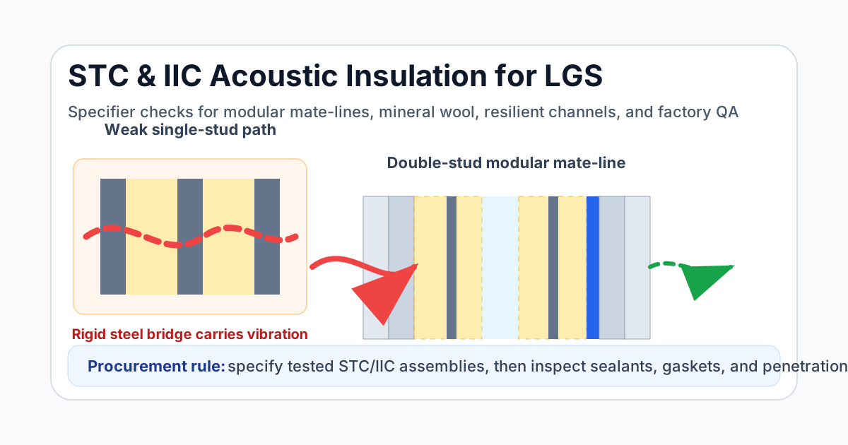
Specify acoustic insulation for LGS modular housing with STC/IIC targets, flanking controls, supplier QA fields, and a technical review CTA from GFK.

Australia Modular Housing Market Update: NSW Approval Changes and Easter Delivery Curfews
Australia modular housing update for 1 April 2026: NSW 14-day modification rules and NHVR Easter curfews reshape approval and delivery decisions.